My old 3D printer MesaXYZ had a hard time printing the X Carriage, it is a complex part and it took over 12h to print (I really need a new 3D printer…). I didn’t use Scott’s original part, but one from Nedalive slightly modified.
The best guide is Scott’s original video, be sure to watch is carefully until you really get to understand how it all fits together.
First I made two Sleeves with PTFE bushings as detailed here. Then the assembly begun…
- This X Carriage does not use Brass Inserts but nuts inserted in appropriate slots, it works very well and insertion is easy as long as it is well cleaned. Just beware not to lose them!
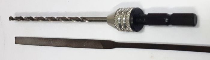
- A lot of cleaning is needed, I used these to make sure that nothing remains in the way where screws or nuts must be inserted:
- I didn’t like the Belt Tensioners, they did not fit right to the adjustment screws. So I made my own, links below in the parts list.


Assembling it all toghether:
- A lot of care should be taken to mount the X Carriage with the X Rods and the XY Carriages, it must move easely even when everything is fixed.
- I needed to insert small aluminum foils (from a soda can, see it in the fictur bellow, out-of-focus), first to make sure that tey are paralel. Don’t tightn it too much, use thread-lock to keep it in place.
- Then to fix in the XY carriages, I used the aluminum inserts here too to fix the rods without flexing them.
- I may look impossible, but it is not!
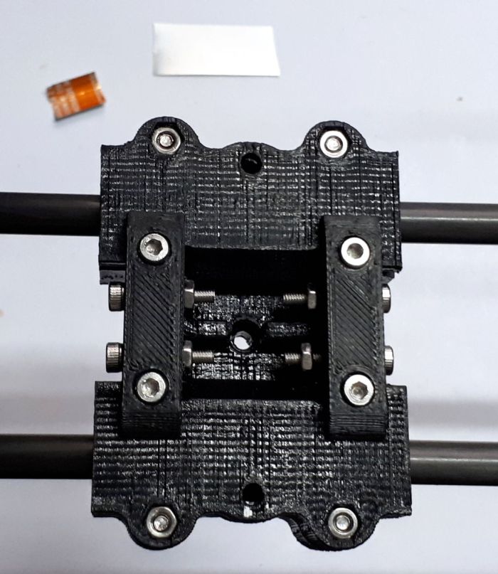
- Belt fixing and tensioning is well explained in Scott’s video and there is nothing noticeable about that. Don’t forget the Belt-Tensioner at the tip of the screws (not present in the picture above.
- Just leave a t least 60mm extra length on both ends for later adjustments. This will be revisited for the final calibration.
- IMPORTANT: don’t leave it assembled without mounting the belts, it may be very fragile in that situation. The belts make sure that it only moves perpendicular to the Y axis.
Used material, printed parts:
- X_Carriage_HCEvo_V2.1c_LM8LUU.stl from Nedalive, modified by Alberto Cabús Junior. Linear bearing now go straight through as if using LM8LUU and the 4 holes for the dowel pins were made a bit smaller to make sure that drilling them will get a perfect alignment. You can get the STL file here.
- 2x Belt_Clamp_v3.stl original from Scott.
- 4x Belt_Tensioner_vA1.stl redesigned by myself. You can get the original at OnShape here, or the STL here. It is very similar, just fits better.
- 2x BushingSupport_vA1.3.stl which is explained here.
- 4x PTFE bushing, details in previous item.
- 4x M3x10 screws, belt clamp
- 4x M3x16 screws, belt adjustment
- 4x M3x20 screws, bearing holders
- 16x M3 nut
- approx. 3m GT2 belt, 6mm, steel core
- 4x M3x30 partial thread screw, it need to be cut to replace the dowel pins, there are spaces for nuts to hold them in place.

Next: Assembling the HotEnd (en), prev: PTFE Bushing for the X axis (en)
